28+ dual slope adc block diagram
Counter Type ADC Block Diagram Integrating Dual-Slope ADC. Each sensor consists of dual electrodes which act as a parallel plate capacitor with an intermediary dielectric layer in the form of the introduced.

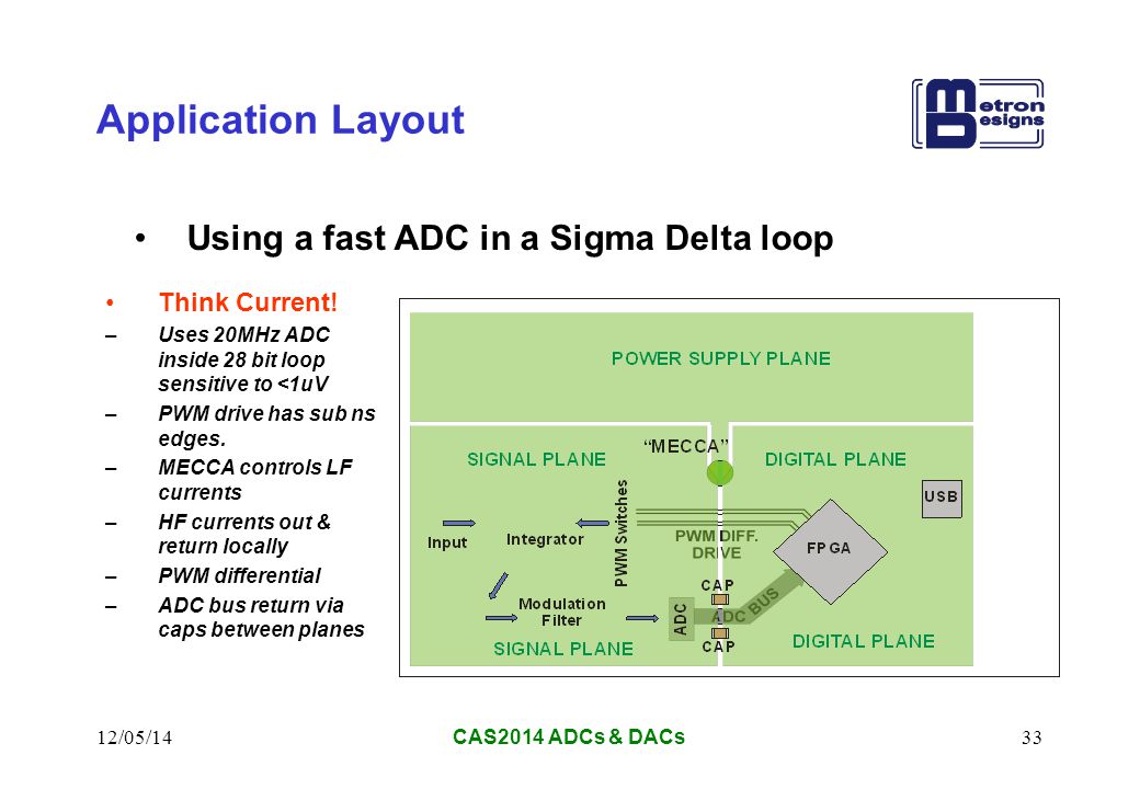
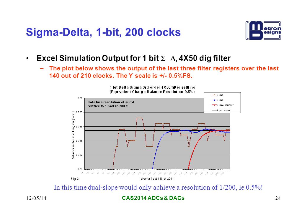
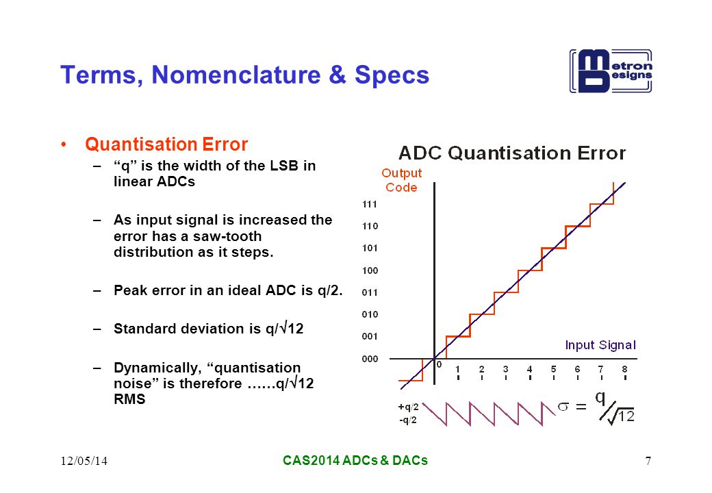
12 05 14cas2014 Adcs Dacs1 Cern Accelerator School Adcs And Dacs Analogue To Digital And Digital To Analogue Converters John Pickering Metron Designs Ppt Download
2The construction is simple and easier to design.
. The Si552 dual frequency VCXO utilizes Silicon Laboratories advanced. The Si552 dual-frequency VCXO utilizes Silicon Laboratories advanced. Articles in Press Accepted.
The conversion of an analog input signal results in a corresponding 10-Bit digital number. Slope determined with V. Choosing the right OPAMP to drive an ADC SAR ADC Bipolar Voltage to Unipolar Voltage ADC Driver.
High-resolution and high-speed fully differential Successive Approximation Register SAR Analog to Digital Converter ADC based on Capacitor Merged Technique is presented in this paper. The equivalent analog output voltage of DAC VD is applied to the non-inverting input of the comparator. Discover all the collections by Givenchy for women men kids and browse the maisons history and heritage.
1It is the fastest type of ADC because the conversion is performed simultaneously through a set of comparators hence referred as flash type ADC. It consists of a successive approximation register SAR DAC and comparator. From 10 to 90 of V.
Choosing the right OPAMP to drive an ADC SAR ADC Bipolar Voltage to Unipolar Voltage ADC Driver. Volume 10 Issue 2 July 2022. Design and Optimization of a Dual Polarized Hat Feed Reflector Antenna.
A mobile radio system base station is installed 50 meters above the ground and transmits 150 W at 54 MHz if the transmitting antenna gain is 517 how far will the receiving antenna be if the antenna height is 30 m and the received field strength is 22 micro Vm. Selectable option by part number. The Analog-to-Digital AD Converter module has 5-Channels for the 28-pin devices and 8-Channels for the 4044-pin devices.
The block diagram of the proposed platform. A universal VCO Board - MC100EL1648DG and PGA-103 A universal XCOPLL Board - NB3N501502511. The output of SAR is given to n-bit DAC.
A universal VCO Board - MC100EL1648DG and PGA-103 A universal XCOPLL Board - NB3N501502511. Antenna heights of. Typical conversion time is 100ns or less.
The functional block diagram of successive approximation type of ADC is shown below.
2

Cern Accelerator School Adcs And Dacs Analogue To

12 05 14cas2014 Adcs Dacs1 Cern Accelerator School Adcs And Dacs Analogue To Digital And Digital To Analogue Converters John Pickering Metron Designs Ppt Download
2

Cern Accelerator School Adcs And Dacs Analogue To
2

12 05 14cas2014 Adcs Dacs1 Cern Accelerator School Adcs And Dacs Analogue To Digital And Digital To Analogue Converters John Pickering Metron Designs Ppt Download

12 05 14cas2014 Adcs Dacs1 Cern Accelerator School Adcs And Dacs Analogue To Digital And Digital To Analogue Converters John Pickering Metron Designs Ppt Download

12 05 14cas2014 Adcs Dacs1 Cern Accelerator School Adcs And Dacs Analogue To Digital And Digital To Analogue Converters John Pickering Metron Designs Ppt Download
2
2

12 05 14cas2014 Adcs Dacs1 Cern Accelerator School Adcs And Dacs Analogue To Digital And Digital To Analogue Converters John Pickering Metron Designs Ppt Download
2
2
2
2

12 05 14cas2014 Adcs Dacs1 Cern Accelerator School Adcs And Dacs Analogue To Digital And Digital To Analogue Converters John Pickering Metron Designs Ppt Download